Home › Unlabelled ›
Solar Power Controller Circuit Diagram - Circuit Diagram of the Solar Battery Charger | Download ... / 50w (4a, 12v nominal) (open circuit voltage:
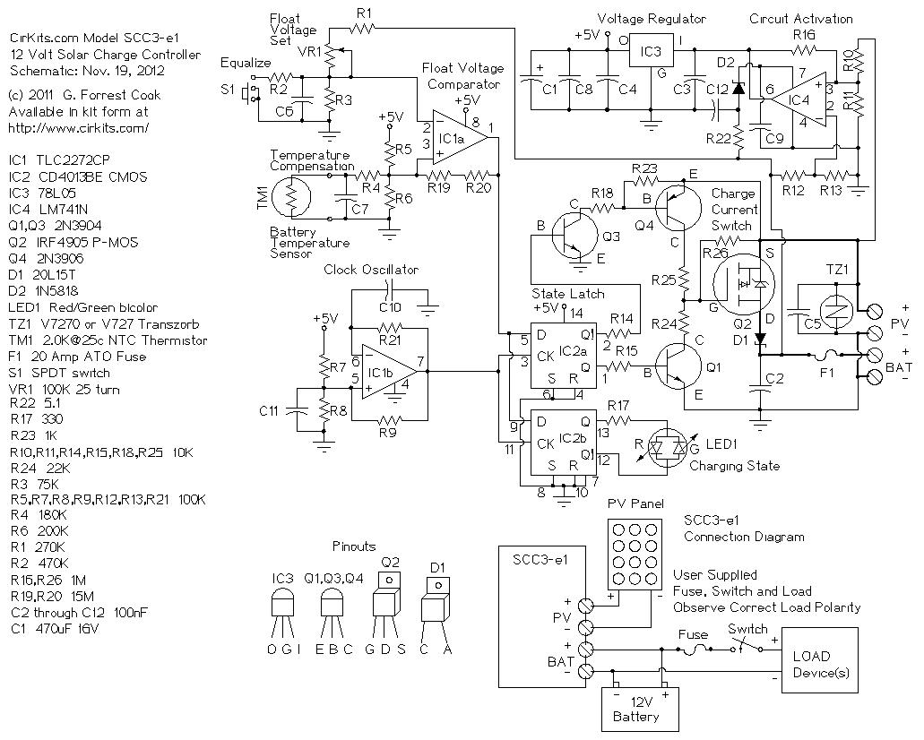
Solar Power Controller Circuit Diagram - Circuit Diagram of the Solar Battery Charger | Download ... / 50w (4a, 12v nominal) (open circuit voltage:. I have posted two versions of my pwm charge controller. In larger solar panel systems designed to power your whole home, panel and battery voltage aren't typically the same. Operational power for this circuit is provided entirely from the pv panel, there is virtually no. Solar power is routed from the pv panel through the 1n5818 schottky diode to the battery. 50w (4a, 12v nominal) (open circuit voltage:
Solar inverter circuit projects circuit diagram alternative energy solar panels solar power homemade circuits simple. 50w (4a, 12v minimal) (open circuit voltage: I have posted two versions of my pwm charge controller. In your suggested scheme, there are two power converters in the path from solar panels to the batteries, whereas in the other model that you mentioned, one power converter, i.e. 16w (includes power dissipation of d3).
Charge Controller Wiring Diagram for DIY Wind Turbine or ... from cdn.instructables.com The mcu requires a 3.3 v source which is obtained from the output of the linear regulator (u11), see. Now a days the most advance solar charge controller are maximum power point tracking (mppt). In your suggested scheme, there are two power converters in the path from solar panels to the batteries, whereas in the other model that you mentioned, one power converter, i.e. The input voltage for the solar controller enters from the solar panel through vin and gnd. Photovoltaic solar panel, module string & arrays wiring & installation diagrams. 16w (encompasses power dissipation of d3) standard dropout voltage: 50w (4a, 12v minimal) (open circuit voltage: I shall not insist upon it.
12 v power supply circuit.
Mppt vs pwm circuit diagram. A global solar charge controller directory with advanced filters that lets you review and compare charge controllers. Home page solar power simulation faq's about solar power easy 5 step guide example systems system overview solar projects solar combiner mini these diagrams are meant to give a general idea of typical system wiring. This circuit of charge controller used analog electronics instead of digital electronics. As a result, pwm controllers are more suited for small diy solar systems. 12 v power supply circuit. Solar inverter circuit projects circuit diagram alternative energy solar panels solar power homemade circuits simple. I have posted two versions of my pwm charge controller. Mppt stands for maximum power point tracking. Mppt charge controller circuit board. These controllers are more expensive than the pwm charge controllers, but it has several mppt circuit is based around a synchronous buck converter circuit. Mppt solar charge controller block diagram. Only 1ma consumption mppt&voltmeter !!!
50w (4a, 12v nominal) (open circuit voltage: I have posted two versions of my pwm charge controller. 50w (4a, 12v minimal) (open circuit voltage: This circuit of charge controller used analog electronics instead of digital electronics. In this article we will try to understand the basic concept of a solar inverter and also how to make a simple yet powerful solar inverter circuit.
12 VOLT 20 AMP SOLAR CHARGE CONTROLLER CIRCUIT DIAGRAM ... from i0.wp.com Mppt stands for maximum power point tracking. The top countries of supplier is. Here sg3524 chip is the primary component to build a solar inverter. *contrary to intuition, solar panels work best at cooler temperatures. The charge controller is only one in the. Photovoltaic solar panel, module string & arrays wiring & installation diagrams. Optimizing this power supply becomes necessary because typically solar panels lack current, but posses excess voltage, this abnormal specs of a solar sir….i want mppt solar charge controller for 50w solar paannel…with variable output voltage…. is an optional filter capacitor.
Transform this power to supply the varying.
The design has an operating efficiency of above 97% at full load in a 24v system. Circuit diagram shown below is simplest circuit diagram of charge controller. Maximum power point tracking (mppt) controller. These controllers are more expensive than the pwm charge controllers, but it has several mppt circuit is based around a synchronous buck converter circuit. In your suggested scheme, there are two power converters in the path from solar panels to the batteries, whereas in the other model that you mentioned, one power converter, i.e. 16w (encompasses power dissipation of d3) standard dropout voltage: 7 to 14v (adjustable) (not recommended for 6v applications). In larger solar panel systems designed to power your whole home, panel and battery voltage aren't typically the same. We have collated charge controller data from manufacturers from all around the world into a common template, allowing you to compare and review charge controllers easily. Mppt charge controller circuit board. is an optional filter capacitor. Mppt stands for maximum power point tracking. *contrary to intuition, solar panels work best at cooler temperatures.
18 to 20v) output voltage range: In your suggested scheme, there are two power converters in the path from solar panels to the batteries, whereas in the other model that you mentioned, one power converter, i.e. The maximum power point tracker (mppt) circuit is based around a synchronous buck converter circuit.it steps the higher solar panel voltage down to the charging voltage of the battery. Controller of solar charger circuit diagram. The input voltage for the solar controller enters from the solar panel through vin and gnd.
Solar Charge Controller Circuit Diagram | The LED flashes ... from i.pinimg.com 965 solar power controller circuit diagram products are offered for sale by suppliers on alibaba.com, of which inverters there are 166 suppliers who sells solar power controller circuit diagram on alibaba.com, mainly located in asia. Circuit diagram shown below is simplest circuit diagram of charge controller. The mcu requires a 3.3 v source which is obtained from the output of the linear regulator (u11), see. Home page solar power simulation faq's about solar power easy 5 step guide example systems system overview solar projects solar combiner mini these diagrams are meant to give a general idea of typical system wiring. 50w (4a, 12v minimal) (open circuit voltage: Mppt charge controller circuit board. Please contact innovatech switching power india to. The most essential charge controller basically controls the device voltage and opens the circuit, halting the charging, when the battery.
In a solar power plant, solar energy is converted into electrical energy by using photovoltaic solar panels and then generated dc in this tutorial, we will show how to make a small solar inverter circuit for home appliances.
Operational power for this circuit is provided entirely from the pv panel, there is virtually no. *contrary to intuition, solar panels work best at cooler temperatures. In larger solar panel systems designed to power your whole home, panel and battery voltage aren't typically the same. 50w (4a, 12v nominal) (open circuit voltage: In this tutorial, i will explain to you about the pwm solar charge controller. Maximum power from the solar panel and then. In a solar power plant, solar energy is converted into electrical energy by using photovoltaic solar panels and then generated dc in this tutorial, we will show how to make a small solar inverter circuit for home appliances. The maximum power point tracker (mppt) circuit is based around a synchronous buck converter circuit.it steps the higher solar panel voltage down to the charging voltage of the battery. Now a days the most advance solar charge controller are maximum power point tracking (mppt). Photovoltaic solar panel, module string & arrays wiring & installation diagrams. The mppt controller is more sophisticated (and more expensive): Is the input of the system which is the power supplied by the solar panel. Circuit diagram shown below is simplest circuit diagram of charge controller.