Home › Unlabelled ›
Wiring Diagram For Ac Thermostat - Diagram Basic Wiring Diagram Home Ac Full Version Hd Quality Home Ac Ardiagramlg Mercatutto It : As shown in the diagram, you will need to power up the thermostat and the 24v ac power is connected to the r and c terminals.
Wiring Diagram For Ac Thermostat - Diagram Basic Wiring Diagram Home Ac Full Version Hd Quality Home Ac Ardiagramlg Mercatutto It : As shown in the diagram, you will need to power up the thermostat and the 24v ac power is connected to the r and c terminals.. Nest thermostat connectors wiring diagrams: Then, set your thermostat on the different modes (ac, heat.) and check what terminals are energized on each function. This video contains 10 wiring diagrams. Furnace thermostat wiring falls in the diy category that a handy type person can hook up or fix. Honeywell thermostat wiring diagram 4 wire.
1 heat / 1 cool thermostat. Before doing any work on the thermostat and wiring take a picture off the wires and their thermostats use 24 volts ac from a transformer to control a furnace. The terminals are usually marked 'r' and 'w'. Nest thermostat connectors wiring diagrams: In thermostat switch we have two types of connection, in which one is for main and in the above diagram i shown how to wire a ref thermostat, but this only a basic diagram and we will publish complete refrigerator diagram soon.
Thermostat Wire Diagram Thermostat Wiring Thermostat Refrigeration And Air Conditioning from i.pinimg.com The following diagram shows the basic thermostat symbols in the simpl windows' programming manager. Check out multiple thermostat wiring diagrams as well as in depth video explanations on accurately wiring colors, terminals, functions, voltage path! That is, you can run the fan without either heating or cooling, just to circulate the air. Air handler, ac separated from furnace, rc and r jumper removed. Always follow manufacturer wiring diagrams as they will supersede these. How to read ac wiring diagram. Heat pump thermostat wiring explained! Always refer to your thermostat or equipment installation guides to verify proper wiring.
Check out multiple thermostat wiring diagrams as well as in depth video explanations on accurately wiring colors, terminals, functions, voltage path!
This will give you a pretty. Rh c rc y z y2 w2 g. Air handler, ac separated from furnace, rc and r jumper removed. Tips:if you need extra temperature sensor. This diagram is to be used as reference for the low voltage control wiring of your heating and ac system. Refer to page 31 for a detailed description of the inputs and outputs. Thermostat installation & wiring diagrams. The following diagram shows the basic thermostat symbols in the simpl windows' programming manager. The other black wire i've yet to figure out where it leads to. Conventional heating/cooling systems wiring diagrams: Furnace thermostat wiring falls in the diy category that a handy type person can hook up or fix. An electrical wiring representation is an easy visual representation of the physical links and physical layout of an electrical system or circuit. Use the wiring diagram and code to attach the wires to the terminals on the thermostat that correspond to the connections on the furnace.
Then, set your thermostat on the different modes (ac, heat.) and check what terminals are energized on each function. Supplies the high side of the 24 volt ac line from the. Refer to the control diagrams in appendix a. Rh c rc y z y2 w2 g. Air handler, ac separated from furnace, rc and r jumper removed.
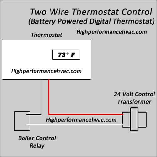
Programmable Thermostat Wiring Diagrams Hvac Control from highperformancehvac.com Heat pump thermostat wiring explained! The following diagram shows the basic thermostat symbols in the simpl windows' programming manager. Heat pump systems wiring diagrams also known as ac integrated dehumidifiers, these systems require cooling to be activated to turn on dehumidification. This video contains 10 wiring diagrams. Always follow manufacturer wiring diagrams as they will supersede these. Tips:if you need extra temperature sensor. This diagram is to be used as reference for the low voltage control wiring of your heating and ac system. In this article, i am going to explain the function and wiring of the most common home climate control thermostats.
Use the wiring diagram and code to attach the wires to the terminals on the thermostat that correspond to the connections on the furnace.
Always follow manufacturer wiring diagrams as they will supersede these. Thermostat installation & wiring diagrams. (this diagram summarizes a thermostat survey's findings: Here's the wiring diagram from the furnace panel Supervision is needed by a licensed hvacr tech while doing this as experience and apprenticeship garners wisdom and safety. Diagrams are available for all warmup thermostats whether you are installing it as part of a. This video contains 10 wiring diagrams. Here is the last bit of theory before we get down to business building the diy arduino thermostat. Nest thermostat connectors wiring diagrams: Check out multiple thermostat wiring diagrams as well as in depth video explanations on accurately wiring colors, terminals, functions, voltage path! If loose, repair or replace the terminal. Before doing any work on the thermostat and wiring take a picture off the wires and their thermostats use 24 volts ac from a transformer to control a furnace. Refer to page 31 for a detailed description of the inputs and outputs.
Always follow manufacturer wiring diagrams as they will supersede these. Here is the last bit of theory before we get down to business building the diy arduino thermostat. Check out multiple thermostat wiring diagrams as well as in depth video explanations on accurately wiring colors, terminals, functions, voltage path! Heat pump systems wiring diagrams also known as ac integrated dehumidifiers, these systems require cooling to be activated to turn on dehumidification. This will give you a pretty.
Diagram For A C Thermostat Wire Diagram Full Version Hd Quality Wire Diagram Diagramcocoz Rome Hotels It from tse2.mm.bing.net Here is the last bit of theory before we get down to business building the diy arduino thermostat. Conventional heating/cooling systems wiring diagrams: Refer to the control diagrams in appendix a. The other black wire i've yet to figure out where it leads to. Attach the yellow wire to the y terminal (ac). Set the heat anticipator for your system. This video contains 10 wiring diagrams. If loose, repair or replace the terminal.
Heat pump thermostat wiring explained!
Installing your ecobee with a boiler and ac (dual transformer system). Thermostat installation & wiring diagrams. The other black wire i've yet to figure out where it leads to. Use the wiring diagram and code to attach the wires to the terminals on the thermostat that correspond to the connections on the furnace. (this diagram summarizes a thermostat survey's findings: Thermostat wiring to a furnace and ac unit! Always follow manufacturer wiring diagrams as they will supersede these. Supervision is needed by a licensed hvacr tech while doing this as experience and apprenticeship garners wisdom and safety. In thermostat switch we have two types of connection, in which one is for main and in the above diagram i shown how to wire a ref thermostat, but this only a basic diagram and we will publish complete refrigerator diagram soon. Air handler, ac separated from furnace, rc and r jumper removed. The following diagram shows the basic thermostat symbols in the simpl windows' programming manager. Check out multiple thermostat wiring diagrams as well as in depth video explanations on accurately wiring colors, terminals, functions, voltage path! Heat pump thermostat wiring explained!